- 您现在的位置:买卖IC网 > Sheet目录334 > ISL8013AEVAL2Z (Intersil)EVAL BOARD 2 FOR ISL8013A
Application Note 1365
ISL8013AEVAL2Z: 3A Low Quiescent Current 1MHz
High Efficiency Synchronous Buck Regulator
? R 1 ?
V OUT = 0.8 ? 1 + ------- ?
R 2 = -------------------------------
V OUT
? ---------------- ? – 1
Description
The ISL8013AEVAL2Z kit is intended for use by
individuals with requirements for Point-of-Load
applications sourcing from 2.7V to 5.5V. The
ISL8013AEVAL2Z evaluation board is used to
demonstrate the performance of the ISL8013A low
quiescent current mode converter.
The ISL8013A is offered in a 4mmx4mm 16 Ld QFN
package with 1mm maximum height. The complete
converter occupies less than 0.4in 2 area. The ISL8014A
is pin-to-pin compatible with the ISL8013A.
Key Features
? High Efficiency Synchronous Buck Regulator with up
to 95% Efficiency
? Power-Good (PG) Output with 1ms Delay
? 2.7V to 5.5V Supply Voltage
? 3% Output Accuracy Over-Temperature/Load/Line
? 3A Guaranteed Output Current
? Start-up with Pre-biased Output
? Internal Digital Soft-Start - 1ms
? Soft-Stop Output Discharge During Disabled
? 35μA Quiescent Supply Current in PFM Mode
? Selectable Forced PWM Mode and PFM Mode
? External Synchronization up to 4MHz
? Less than 1μA Logic Controlled Shutdown Current
? 100% Maximum Duty Cycle for Lowest Dropout
? Internal Current Mode Compensation
? Peak Current Limiting and Hiccup Mode Short Circuit
Protection
? Over-Temperature Protection
Quick Setup Guide
1. Ensure that the circuit is correctly connected to the
supply and loads prior to applying any power.
2. Connect the bias supply to VIN. Plus terminal to P4
(VIN) and negative return to P5 (GND).
3. Verify that position is ON for SW1.
4. Turn on the power supply.
5. Verify the output voltage is 1.8V for V OUT
Evaluating the Other Output Voltage
The ISL8013AEVAL2Z kit output is preset to 1.8V;
however, output voltages can be adjusted from 0.8V to
3.3V using Equations 1 and 2:
(EQ. 1)
? R 2 ?
Let’s set R 1 = 124k Ω
( R 1 )
(EQ. 2)
? 0.8 ?
Note: If desired output is 0.8V, then short R 1 and open
R 2 .
Mode Control
The ISL8013A has a SKIP pin that controls the operation
mode. When the SKIP pin is driven to low or shorted to
ground, the regulator operates in a PFM mode. Set SKIP
pin high forced PWM mode. The controller remains in the
fixed PWM frequency at light load instead of entering the
skip mode. In an application where a situation requires
the ISL8013A regulator to sink more than 2A valley
inductor current, it is recommended to operate in PFM to
avoid any possible over stress.
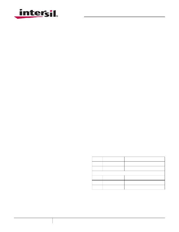
TABLE 1. SWITCH 1 SETTINGS
Recommended Equipment
The following materials are recommended to perform
testing:
? 0V to 10V Power Supply with at least 5A source
current capability or 5V battery
? Electronic Loads capable of sinking current up to 5A
? Digital Multimeters (DMMs)
? 100MHz quad-trace oscilloscope
SW1
1
3
SW2
1
3
ENABLE
OFF
ON
SKIP
PWM
PFM
ON/OFF CONTROL
Disable V OUT
Enable V OUT
FUNCTION
Fixed PWM frequency at light load
Force continuous mode
? Signal generator
December 16, 2009
AN1365.3
1
CAUTION: These devices are sensitive to electrostatic discharge; follow proper IC Handling Procedures.
1-888-INTERSIL or 1-888-468-3774 | Intersil (and design) is a registered trademark of Intersil Americas Inc.
Copyright Intersil Americas Inc. 2007, 2008, 2009. All Rights Reserved
All other trademarks mentioned are the property of their respective owners.
发布紧急采购,3分钟左右您将得到回复。
相关PDF资料
ISL8014AEVAL2Z
EVAL BOARD 2 FOR ISL8014A
ISL8022EVAL2Z
EVAL BOARD 2 FOR ISL8023
ISL8088EVAL2Z
EVAL BAORD FOR ISL8088
ISL8105BEVAL2Z
EVALUATION BOARD FOR ISL8105B
ISL8112EVAL1Z
EVALUATION BOARD FOR ISL8112
ISL8206MEVAL1Z
EVAL BOARD 1 FOR ISL8206
ISL83202IPZ
IC FET DRIVER H-BRIDGE 1A 16-DIP
ISL83204AIPZ
IC FET DVR 60V/2.5A HF 20-PDIP
相关代理商/技术参数
ISL8013AIRZ
功能描述:直流/直流开关调节器 3A LW QUIESCENT CUR 1 6MHZ 4X4 16LD RoHS:否 制造商:International Rectifier 最大输入电压:21 V 开关频率:1.5 MHz 输出电压:0.5 V to 0.86 V 输出电流:4 A 输出端数量: 最大工作温度: 安装风格:SMD/SMT 封装 / 箱体:PQFN 4 x 5
ISL8013AIRZ-T
功能描述:IC REG BUCK SYNC ADJ 3A 16QFN RoHS:是 类别:集成电路 (IC) >> PMIC - 稳压器 - DC DC 开关稳压器 系列:- 产品培训模块:Lead (SnPb) Finish for COTS
Obsolescence Mitigation Program 标准包装:2,500 系列:- 类型:降压(降压) 输出类型:两者兼有 输出数:1 输出电压:5V,1 V ~ 10 V 输入电压:3.5 V ~ 28 V PWM 型:电流模式 频率 - 开关:220kHz ~ 1MHz 电流 - 输出:600mA 同步整流器:无 工作温度:-40°C ~ 125°C 安装类型:表面贴装 封装/外壳:16-SSOP(0.154",3.90mm 宽) 包装:带卷 (TR) 供应商设备封装:16-QSOP
ISL8013AIRZ-T7A
功能描述:IC REG BUCK SYNC ADJ 3A 16QFN RoHS:是 类别:集成电路 (IC) >> PMIC - 稳压器 - DC DC 开关稳压器 系列:- 产品培训模块:Lead (SnPb) Finish for COTS
Obsolescence Mitigation Program 标准包装:2,500 系列:- 类型:降压(降压) 输出类型:两者兼有 输出数:1 输出电压:5V,1 V ~ 10 V 输入电压:3.5 V ~ 28 V PWM 型:电流模式 频率 - 开关:220kHz ~ 1MHz 电流 - 输出:600mA 同步整流器:无 工作温度:-40°C ~ 125°C 安装类型:表面贴装 封装/外壳:16-SSOP(0.154",3.90mm 宽) 包装:带卷 (TR) 供应商设备封装:16-QSOP
ISL8013EVAL2Z
功能描述:EVALUATION BOARD FOR ISL8013 RoHS:是 类别:编程器,开发系统 >> 评估板 - DC/DC 与 AC/DC(离线)SMPS 系列:- 产品培训模块:Obsolescence Mitigation Program 标准包装:1 系列:True Shutdown™ 主要目的:DC/DC,步升 输出及类型:1,非隔离 功率 - 输出:- 输出电压:- 电流 - 输出:1A 输入电压:2.5 V ~ 5.5 V 稳压器拓扑结构:升压 频率 - 开关:3MHz 板类型:完全填充 已供物品:板 已用 IC / 零件:MAX8969
ISL8013IRZ
功能描述:直流/直流开关转换器 3A LW QUIESCENT CUR 1 6MHZ 4X4 16LD RoHS:否 制造商:STMicroelectronics 最大输入电压:4.5 V 开关频率:1.5 MHz 输出电压:4.6 V 输出电流:250 mA 输出端数量:2 最大工作温度:+ 85 C 安装风格:SMD/SMT
ISL8013IRZS2715
制造商:Intersil Corporation 功能描述:S SPEC FOR TRACKING BROADCOM BUSINESS ONLY-SOLD THRU DISTI - Rail/Tube
ISL8013IRZ-T
功能描述:IC REG BUCK SYNC ADJ 3A 16QFN RoHS:是 类别:集成电路 (IC) >> PMIC - 稳压器 - DC DC 开关稳压器 系列:- 产品培训模块:Lead (SnPb) Finish for COTS
Obsolescence Mitigation Program 标准包装:50 系列:- 类型:升压(升压) 输出类型:两者兼有 输出数:1 输出电压:5V,2 V ~ 16.5 V 输入电压:2 V ~ 16.5 V PWM 型:- 频率 - 开关:45kHz 电流 - 输出:50mA 同步整流器:无 工作温度:0°C ~ 70°C 安装类型:通孔 封装/外壳:8-DIP(0.300",7.62mm) 包装:管件 供应商设备封装:8-PDIP
ISL8013IRZ-TS2715
制造商:Intersil Corporation 功能描述:S SPEC FOR TRACKING BROADCOM BUSINESS ONLY-SOLD THRU DISTI - Tape and Reel
